The End-To-End Tutorial
After all the background and methodology, it's time to get our hands dirty. For this tutorial, we will use as many freely accessible tools (such as Open Source) as possible to make the material more accessible. You will need the following software installed on your Linux/Windows/Mac environment:
- Data Modelling: Enterprise Architect 12.0
- Schema Transformation: ShapeChange 2.1.0 (Open Source)
- Data Transformation: hale studio 2.9.4 (Open Source)
- Service Publishing: deegree 3.3.18 (Open Source)
You also need a test data set to play around with in later stages of the project. We're going to use an SQLite CDDA data set that we can download from the European Environmental Agency .
| In this tutorial, we build a custom variant of the existing CDDA INSPIRE extension. If you need to deliver CDDA data, please use the official extension, and not a custom variant we might build using this tutorial. |
Analysis
It's late on a rainy Friday afternoon. I am in the middle of reviewing an article when my boss Alex calls. He sounds agitated and tells me that there is a problem, so he needs me to help him. Ten minutes later, we sit together at the bar of the pub across the road. Alex tells me about the meeting he has had in the last two days in the capitol city, with many other directors of public authorities.
After ordering our drinks, Alex starts to tell me what bothers him: «We're being blamed for lack of progress on two projects. The ministry is under pressure from the EU, because of our lack of progress in INSPIRE implementation. In addition, after last year's new legal act, we're supposed to implement a new protected sites reporting system using the Common Database on Designated Areas (CDDA) standard, but we haven't made any headway on this one either. After the meeting yesterday, we at least have some funding for the CDDA project, though there is almost no budget for INSPIRE. I need you to take over the protected sites implementation project, while I will figure out how to fund the INSPIRE project.» I listen to his explanations for a few more moments, then I interrupt him: «You know what? Give me both your problem projects. I have an idea how we can make both work at the same time, with one budget! Do I have your support?»
Two weeks later, I've assembled my team. I've got three domain experts from nature conservation, Chris, who is an integration expert and Thorbjörn, who is an ETL expert. It was really hard to get some of them on board - everybody is tied up in their daily projects, and some were not exactly keen on INSPIRE. In our first meeting, we analyse relevant documents and take a look at the model patterns. We quickly decide that we will use the INSPIRE extension pattern, which means that whatever model we design, our model is not allowed to make compatibility-breaking changes.
After you've set up your team and got organised, your team's first step is to perform an analysis on the requirements for the extended data model. These requirements come from various sources, such as legal texts or implementation rules. The following text example describes CDDA:
The Common Database on Designated Areas (CDDA) is more commonly known as Nationally designated areas. The inventory began in 1995 under the CORINE programme of the European Commission. It is now one of the agreed Eionet priority data flows maintained by EEA with support from the European Topic Centre on Biological Diversity. It is a result of an annual data flow through Eionet countries. The EEA publishes the data set and makes it available to the World Database of Protected Areas (WDPA). The CDDA data can also be queried online in the European Nature Information System (EUNIS).
The database is divided into a national area and an international area. The national area is for member states of the EU or EEA about the European Environment Information and Observation Network or EIONET. Data cleansing for the national area of non-EEA members and the international area is carried out by UNEP-WCMC systems. The database follows the system of the International Union for Conservation of Nature and Natural Resources (IUCN) and the standards of the United Nations in order to ensure compatibility with similar data banks worldwide, especially the World Database on Protected Areas (WDPA).
The EEA also provides an Excel tables that describes the data model in detail. From these tables, we learn that the final data model will need to contain information on the following properties of designated areas:
- Designations need to be described by providing an ISO ALPHA-3 code of the reporting country, the ISO ALPHA-3 code of the country where the data originate from, a national designation type code, the title of the designation in the original language and in English, a reference to the legal text covering the designation as well as a Reference to the Official Journal where the law was published. Furthermore, the Designation need to have the address of the administrative authority responsible for the designation, the total number of sites and the total area in hectares covered for this designation. Finally, there should be space for remarks concerning the designation.
- Designated Sites have a Unique record identifier for nationally designated areas, a national site code, an ISO ALPHA-3 code of the reporting country, the ISO ALPHA-3 code of the country where the data originate from, a National designation type code, a name of the site in local language and the surface area of site in hectares. They are also described through a IUCN management category, the year of establishment (when the site was first time designated), and the year and code of the last legal change. The location is indicated by geographical latitude (x, y) in decimal degrees format. Finally, each record also contains information on licensing and remarks on the site record.
The table describes additional potential classes for our model, such as Designation Boundaries, Site Boundaries and a National Overview.
Finding your scope and comparing to existing specifications
In a first step, we need to identify which INSPIRE data specifications are a good match for our extension project. We use the Interactive Data Specifications Find your Scope tool for this purpose. We start with a Direct search, where we enter «Designation»:
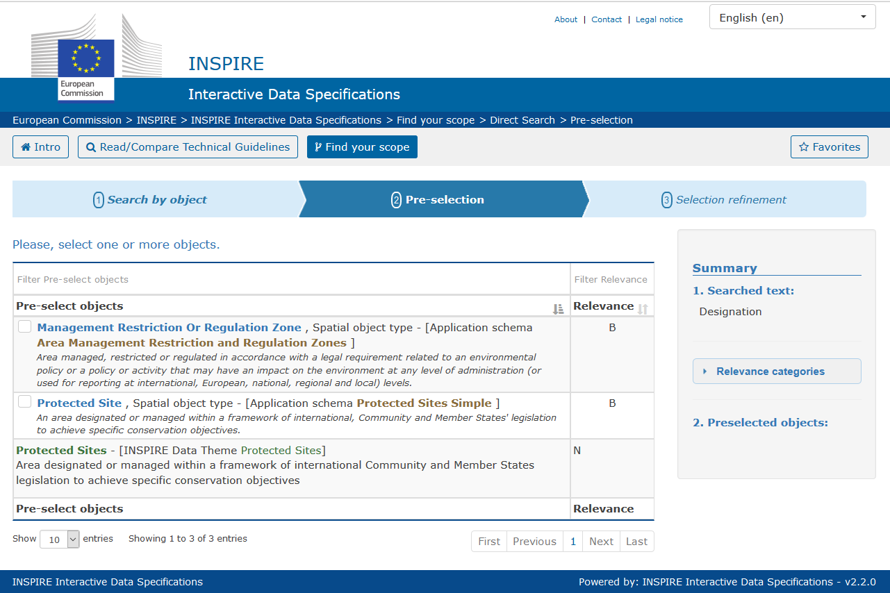
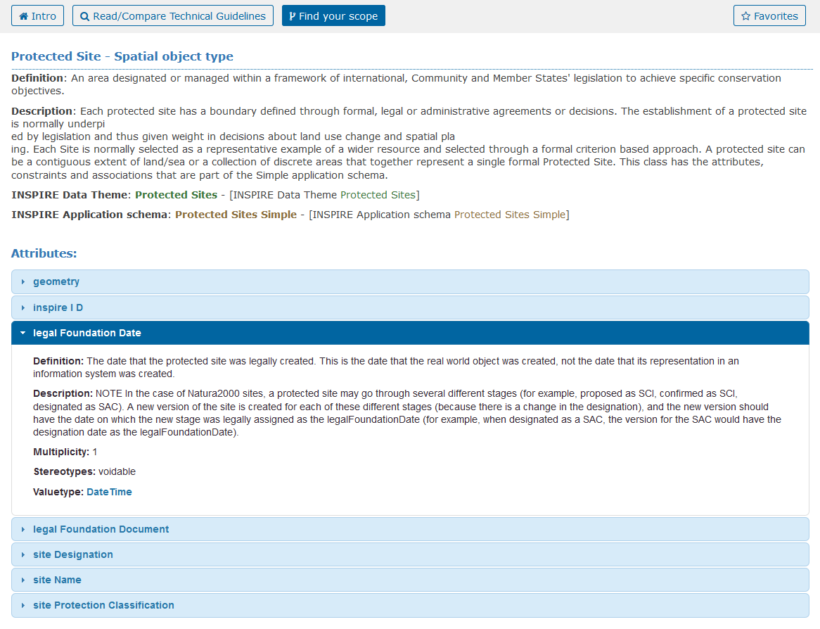
We get a couple of direct hits, among them the theme «Protected Sites» and the spatial object type Protected Site. Since we're going to deal with protected sites, let's look at that in detail. We click on the name, and learn that this type has several relevant properties such as legalFoundationDate and legalFoundationDocument, both of which are required in the CDDA definition:
Next, we do a complete comparison of the requirements of our CDDA model extension with the INSPIRE Protected Sites model. This comparison results in the following coverage table:
| Requirement | Covered | Not covered |
|---|---|---|
| IE-01 Designation Type | The required Type Designation Type can be matched to the to the INSPIRE data type DesignationType. We can use designationScheme to indicate the CDDA/IUCN designation, and use designation for the name of the designation. |
All other properties - such as country codes, a citation for the responsible authority and statistical summaries - need to be added. |
| IE-02 Designated Areas Type | The required type Designated Area can be matched to the INSPIRE spatial object type Protected Site. We can use the legalFoundationDate and legalFoundationDocument properties to indicate when a new site was formed, and what the legal foundation was for its formation. We use siteName to cover the naming requirements in multiple languages. |
There are several properties that CDDA requires which the ProtectedSites object type does not cover. These include remarks and data dissemination rules, the ISO country codes, the IUCN category, the major ecosystem type, an indication of the marine area, the national ID, the type of protected area, a representative point geometry, a resolution code and information on availability of additional spatial data. |
Extension Design (Modelling)
We now know exactly what we need to add to the INSPIRE data specification, but we don't yet know how we should do it. I organise a two-day meeting with the others of my working group in a somewhat remote location, in the hopes of getting everyone's full attention. After the usual agenda setting and introductions, we directly start working. First of all, we prioritize requirements and then start with the most important requirement. For each requirement, everybody on the team gets three minutes to decide how he or she would design a model for that requirement, using any tools they prefer. Most of us simply draw on the ample whiteboards we have in the room. Everybody then presents their design, and the others give feedback about aspects they like or dislike. During all the time, I note down the likes and dislikes, and consolidate them into a single conceptual model using a UML modelling software. After an intense day, we've gone through all requirements. While the others are off to enjoy a well-deserved beer on the patio, I finalize the integrated draft model.
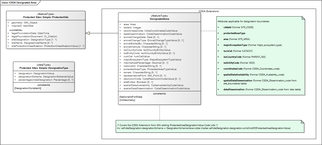
One of the key challenges we have to resolve is to pick the right extension pattern. We discuss two main extension patterns - Inheritance and Association. The main difference is that when we use inheritance, we will have a single object that complies to the requirements of the INSPIRE, while when we use Association, we will have two objects, where the DesignatedArea object will reference the ProtectedSite object. This is what the UML model for the Inheritance approach looks like:
This is what the comparable UML model for the Association approach looks like:
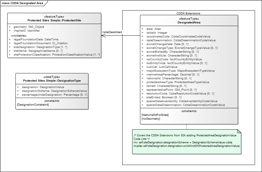
In the end, we decide to use the association approach, so that the core INSPIRE ProtectedSite object can also be used independent of all the CDDA-related properties.
Set up the Extension Model
To create the association-based UML model in Enterprise Architect, proceed as follows:
- Download the INSPIRE UML model as a EA file from the INSPIRE site.
- Start Enterprise Architect and open the INSPIRE UML model. Since you loaded the existing INSPIRE model, you will also automatically use the «UML Profile for INSPIRE».
- Save the model to a new name to represent your extension. In this example, use
CDDA. - In the Project Browser, click on «Add Model» to create a new Model. In the Model Wizard, click on «Geospatial» and then select «GML Application Schema». Call the new model
CDDA Designated Area.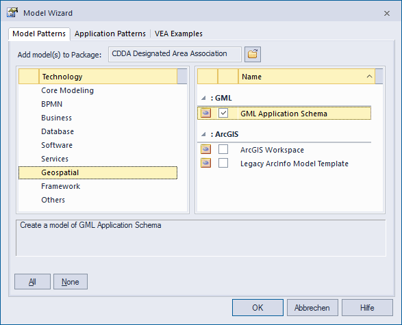
- In the Project Browser, click on «Add Package» to create a new Package in the Model you just created. Call the package
CDDA Designated Area. - In the Project Browser, right-click on the new package and click on «Properties». In this window, set the stereotype property to
applicationSchema. This helps Shapechange later on to identify for which packages it needs to generate GML application schemas for.Furthermore, go to the «UML Profile for INSPIRE» tab and set the values of the properties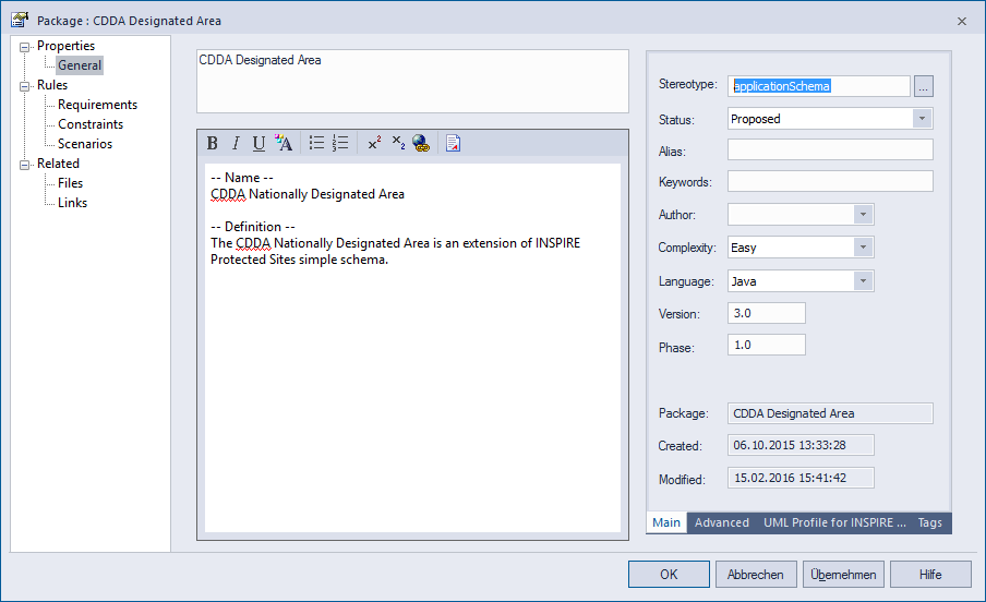
targetNamespace,version,xmlnsandxsdDocument. - In the Project Browser, right-click on the new package and click on «Add Diagram...». Select «UML Structural» and then select «Class Diagram». Give the diagram a name, such as
CDDA Designated Area, and then open the diagram.
Now, you have a canvas on which to model your extension. First, let's pull in the types from the INSPIRE model that we want to use in our extension:
- In the Project Browser, expand the «INSPIRE Consolidated UML Model»
- Then, go to «Themes», «Annex I», «Protected Sites», «Protected Sites Simple».
- Select the feature type
ProtectedSite, and drag and drop it into your new diagram. - Select the data type
DesignationType, and drag and drop it into your new diagram.
Add a new Type and new properties
The next step is to add your own extension by creating a new type. Proceed as follows:
- From the Toolbox, drag a Class into your drawing. Call it
DesignatedArea. - Set the stereotype of the new class to
featureType. - Make sure the values for the «UML profile for INSPIRE» are set as follows:
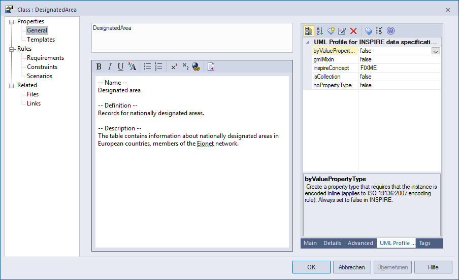
- Confirm with «OK».
Your new DesignatedArea now needs to be associated with the ProtectedSite class:
- In the diagram, select the new
DesignatedAreaclass. On the top right hand side of the class, an arrow appear. Click and press on that arrow and drag its tip over to theProtectedSiteclass. - A popup appears. Pick «Association».
- Double-click on the newly created association to edit its properties. Go to the Role(s) category and configure the target role as follows:
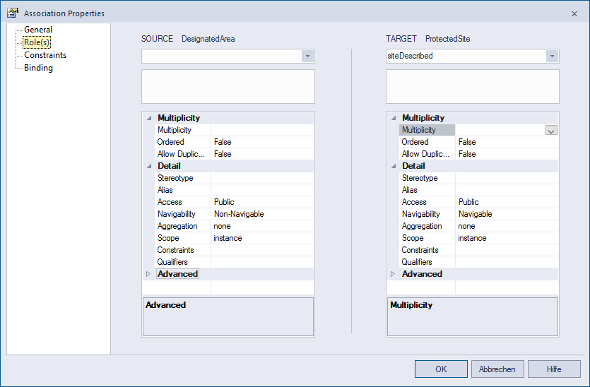
- Confirm with «OK».
Now, we can add all the missing properties, one by one. Repeat the following process for all missing properties:
- Right-click on the
DesignatedAreaclass. Go to «Features & Properties» and click on «Attributes...». - Click on «New Attribute» and enter the name of the Attribute, such as
remark. - Click on the «Type» column, and pick «Select Type...».
- Go to the Search category, and type in
CharacterString. You will see several results:Pick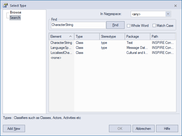
CharacterString. Instead of just typing something or picking one of the inbuilt primitive types, you should always first search whether a possible type you can use exists already in the INSPIRE and ISO models, like in this case. Re-using these types for properties helps tremendously with ensuring a compatible encoding. - Change the value in the «Scope» column to
Public. - Make sure that you set the Multiplicity to the required value, e.g.
[1..*].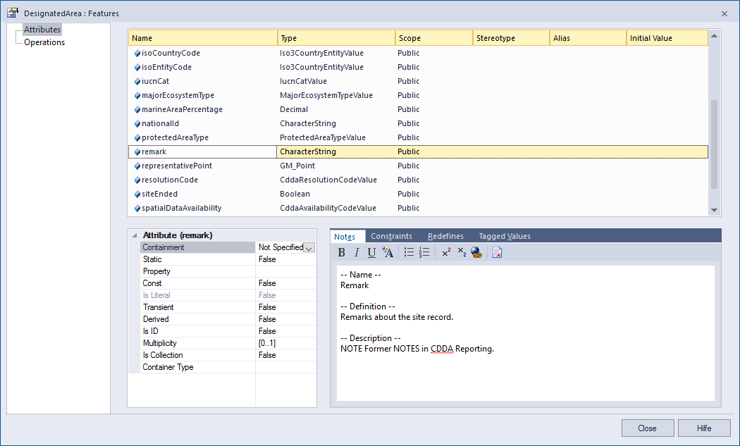
- Confirm with «Close».
Add a new codelist
In some cases, there won't be an appropriate type to use for a property. You will have to create it yourself. In the CDDA model, it is particularity common that we need to add or extend codelists. The following process describes how to add a new code list and needs to be repeated for each such code list type:
- From the Toolbox, drag a Class into your drawing. Call it
CddaResolutionCodeValue. - Set the stereotype of the new class to
codeList. - Make sure the values for the «UML profile for INSPIRE» are set as follows:
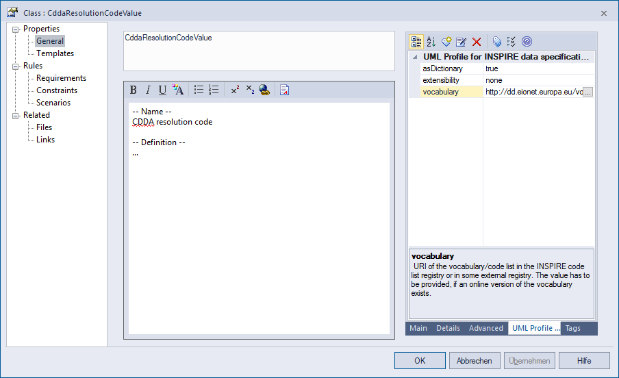
- Confirm with «OK».
- To add individual coded values to the codelist, go to «Features & Properties» and click on «Attributes...». Create coded values in the same way you created attributes:
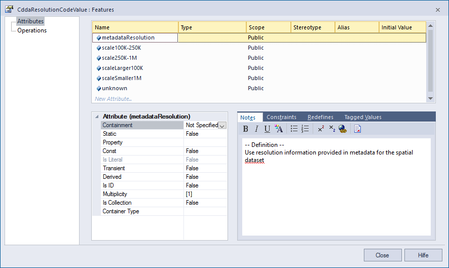
- Confirm creation of coded values with «Close».
- Now that you have created the new codelist type, you can use it as an attribute type in the
DesignatedAreaclass.
Extend an existing codelist
To extend a code list in UML, go through these steps:
- In the Project Browser, navigate to the «Protected Sites Simple» schema, select
DesignationSchemeValueand drag it into the diagram. - From the Toolbox, drag a Class into your drawing. Call it
DesignationSchemeValueas well, so that is can substitute the original code list later on. - Set the stereotype of the new class
DesignationSchemeValuetocodeList. Also, make sure that the required values for the «UML profile for INSPIRE» are set: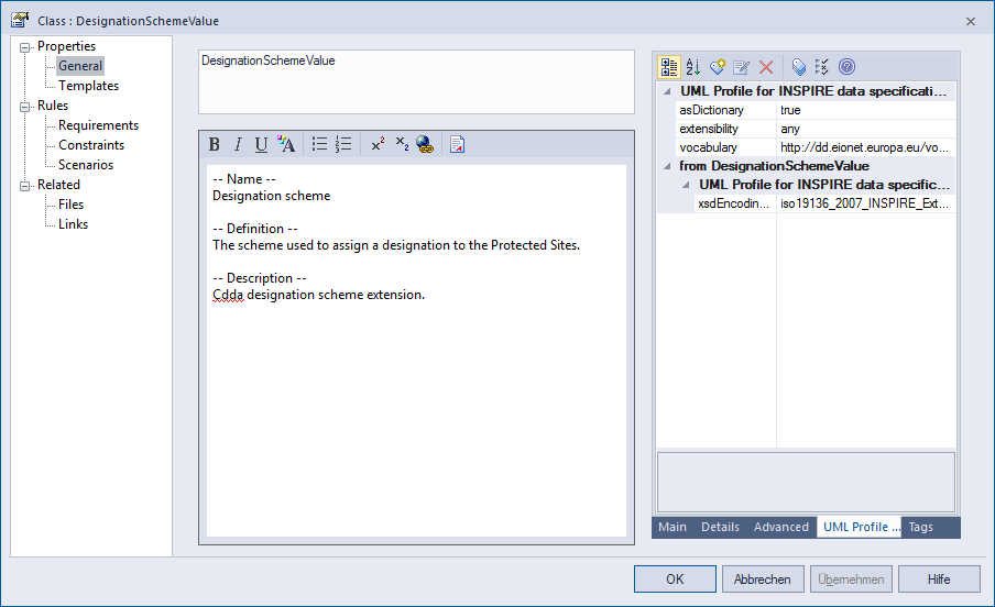
- Click on the new class
DesignationSchemeValue, then click and drag the arrow that appears on the top right of the class. Drop it on the original INSPIREDesignationSchemeValuecodelist, and pickGeneralizationfrom the pop-up menu. - Confirm with «OK».
- Add additional coded values to the codelist. Go to «Features & Properties» and click on «Attributes...». Create coded values in the same way you created attributes.
- Confirm creation of coded values with «Close». Your new codelist should now look like this in the UML diagram:
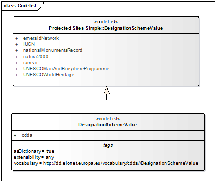
- Now that you have created the new Codelist type, you can use it as an attribute type in the
DesignatedAreaclass.
When you have repeated these steps for all required properties, we get the following model:
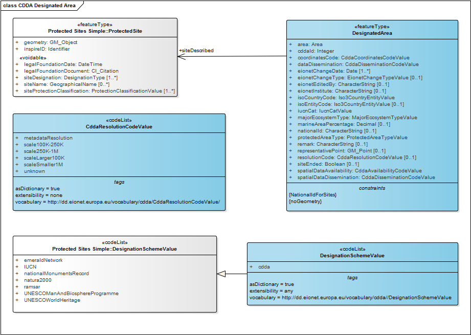
Validation
After the first day of the workshop, we've already drafted a first, rough model that covers most requirements. Before we hammer out all the details, I ask Chris, our integration expert, and Thorbjörn, the ETL expert, to quickly create a first prototype, so that we can learn what our data will look like. This is what they did:
Vertical Mapping
Our goal is now to see whether we can use the conceptual model we've designed to store and serve Designated Areas effectively. We thus create two logical models based on the conceptual model:
- The GML Application Schema, which we need to provide Download Services
- A PostgreSQL Database Schema, which we need to provide persistent storage for the Designated Areas
We will use Shapechange to create these two logical schemas. Make sure that Shapechange works correctly as per the instructions, and that the Enterprise Architect integration also works by following the steps in the Shapechange manual. We first generate the GML Application Schema. To do so, we need to create a configuration file for Shapechange first. Proceed as follows:
- Open a programmer's text editor, such as Notepad++.
- In the editor, open the example INSPIRE GML configuration provided with Shapechange. The first lines of that configuration files look like this:
- In line 4, set the value of the parameter
inputFileto the path where your EAP model file resides. Make sure to use a Unix path (e.g. using single forward slashes). - In line 5, set the name of your model as you would like to call it.
- The parameter
appSchemaNamespaceRegexin line 6 allows you to limit for which namespaces Shapechange will generate XSDs. Set this to the namespace you used when creating the model, e.g.^http://dd.eionet.europa.eu/.* - You should also review the rest of the configuration. You might want to adjust the output path (
outputDirectory), and you might need additionalxsdMapEntries. These entries allow you to tell Shapechange which UML types (classes) map to which GML elements.
To execute Shapechange and generate the GML schema, we will create a little shell script so that we will not wonder the next time we need to generate a schema how we did it. Complete these steps:
- Open a programmer's text editor, such as Notepad++.
- If you're on Windows, open the
test.batscript that came with Shapechange, otherwise open thetest.shfile. In that file, you can see a call to execute Shapechange using Java:#!/bin/sh java -jar ShapeChange-2.1.0.jar -Dfile.encoding=UTF-8 -c http://shapechange.net/resources/test/testXMI.xml - Change that file so that the path points to the configuration file we've created previously.
- Save the modified file under a new name in the same folder, e.g.
inspire-extension-cdda.sh - Open up a console window and navigate to your installation directory of Shapechange.
- Run the script you've created previously:
./inspire-extension-cdda.sh - Assuming there were no errors in the configuration file, you now have an output folder with a log file and with the resulting GML Application Schema!
Second, we generate a database schema for PostgreSQL. We do so by adding an additional transformation target to the existing Shapechange configuration:
- In the programmer's text editor, open the configuration file we've created earlier. The later lines of that configuration file contain the definition of multiple output targets. We're going to add one for the generation of SQL, so that the file looks like this:
- Make sure you adjust the output directory (Line 15). Also, set the Identifier of the spatial reference system you'd like to use to the correct value (Line 17).
- Save the file and re-run Shapechange as per the instructions above.
Data Integration
After creating the target schemas, it's now time for us to see what real data using these schemas looks like. Since the end product we need to create is INSPIRE GML, we will start with data integration into the GML Application Schema. We will use hale studio 2.9.4+ for that purpose.
In hale studio, we define a transformation by mapping elements of a source schema to elements of the target schema. The sum of these mappings is called an Alignment. The source schema is the logical model of our existing data. In this case, we use a SQlite CDDA database (450MB) as source data. The target schema is the GML Application Schema we've just generated. Let's start hale studio and set up the transformation project first:
- In hale, click on File → Import → Source Schema, and click «Browse» to pick the SQLite file you've downloaded.
- Next, click on File → Import → Target Schema, and click «Browse» to pick the GML Application Schema file you've generated before. Click «Finish».
- Now, add the imported type
ProtectedSiteto the mappable types, so that it is visible as part of the target schema. In the main tool bar, go to the icon (title: Edit mapping relevant target types). IN the dialog that appears, enter
 ProtectedSitein the search bar and pick the type from the field below. After you've addedProtectedSite, your project should look like this: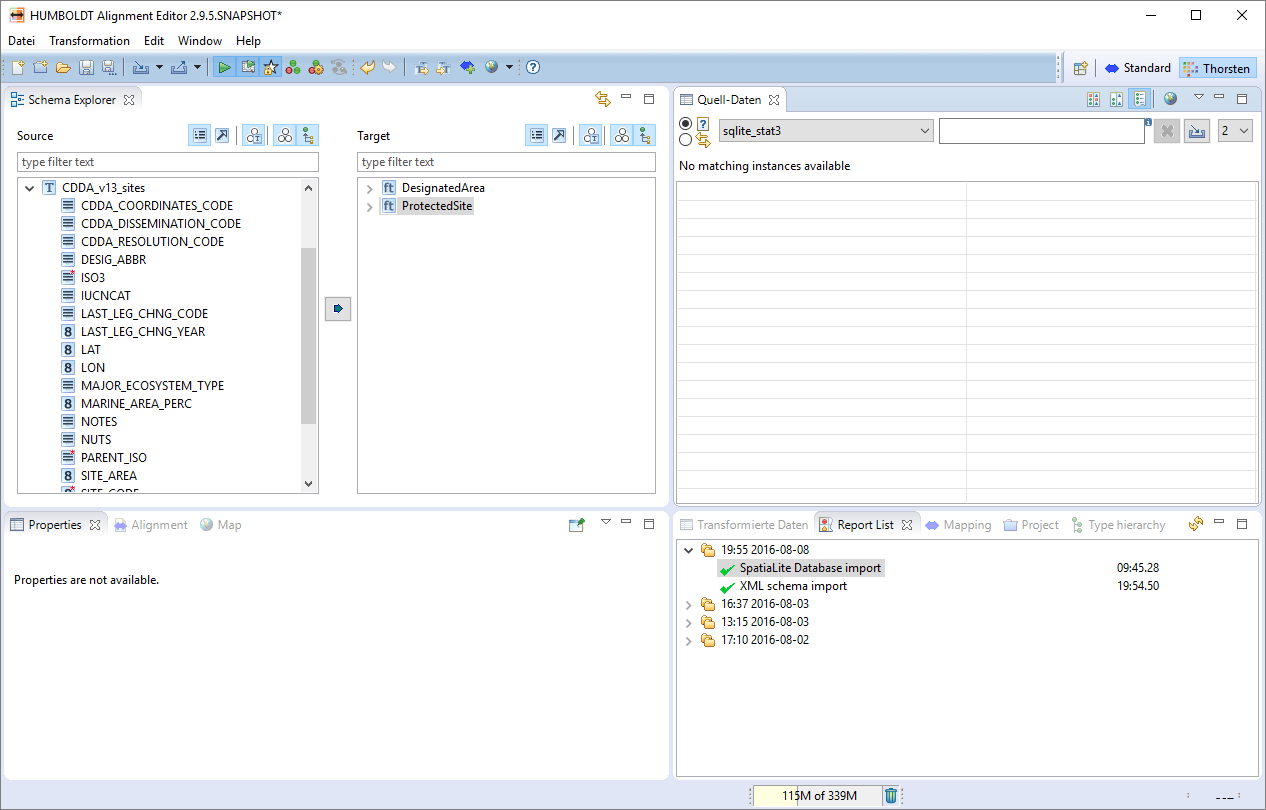
- In hale, you can use a data set to do live transformation and validation while you author the alignment. To enable this feature, activate «instance sampling» by clicking the left of the two icons in the red box:
You can click on the right icon to configure the sampling, e.g. to indicate with how many feature you'd like to work.

- Next, we need to load the actual source data to work with. Go to File → Import → Source Data, and click «Browse» to pick the SQLite file you've downloaded. Note that if you click the List icon left of the file input field, you can chose from the most recent files you've worked with - your SQLite DB will also be among them.
Now, it is time to set up the alignment itself. In hale, we have two different levels of transformation functions:
- Type-level functions: These are used on entire objects, e.g. a
ProtectedSite. - Property-level functions: These are used on individual properties of objects, e.g. an
idof aProtectedSite.
We start by defining the type-level functions first:
- On the left-hand source side, select
CDDA_v13_sites, on the right-hand target side, selectProtectedSite. - Click on the double-arrow icon
 in the middle between the source and the target schema. Hale studio now suggests a number of applicable functions. Pick «Retype» and then click «Finish». «Retype» is a simple function that creates one target object for each source object. hale studio now runs the transformation and validates the output. Your project should look like this:
Do you see all the numbers next to the elements of the source schema and the
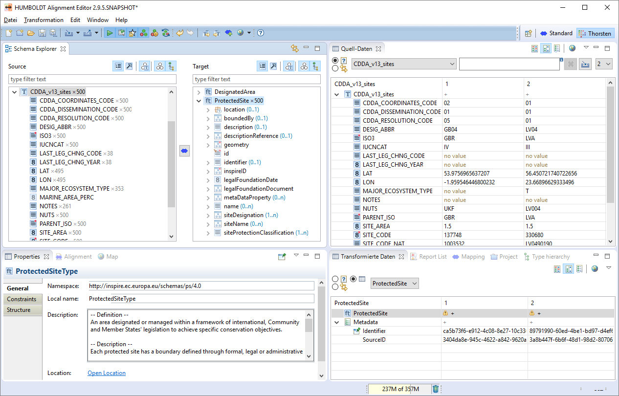
ProtectedSitetype in the target schema? This is how the application tells you for which parts of the source and target schema features data is currently loaded and transformed. - On the left-hand source side, select
CDDA_v13_sites, on the right-hand target side, selectDesignatedArea.. - Click on the double-arrow icon
 in the middle between the source and the target schema and pick «Retype», then click «Finish». Again, the transformation is executed.
 - Now it's time to take a look at the validation results that the software generated. In the «Report List» view, click on the top-most report called «Instance validation». In the «Properties View», you'll see a summary of the validation. To get more details, click on «Warnings» to see the following information:

These warnings indicate that the ProtectedSite and DesignatedArea objects we've now created miss several required properties. To resolve all these warning, we need to create these required properties correctly. We do so by using property-level transformation functions:
- On the left-hand source side, select the property
SITE_AREAin the typeCDDA_v13_sites, on the right-hand target side, select the propertyareain the typeDesignatedArea. - Click on the double-arrow icon
 and pick «Rename», then click «Finish». «Rename» is an all-purpose transformation function that copies the value from the source property to the target property, and applies any required conversions, e.g. from
 NumbertoString. - Take a look at the validation report details again. You will now find that while the message related to
areais gone, there is a new message foruom(Unit of Measurement), an attribute of theareaproperty. - On the right-hand target side, select the attribute
uomof the propertyareain the typeDesignatedArea. - Click on the double-arrow icon
 and pick «Assign». Assign is a function with which you can write a constant value to a target property. Click «Next», then enter
 har(code for hectares) into the text input field:Click «Finish», and see the transformation and validation execute.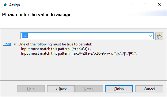
- On the left-hand source side, select the properties
LATandLONin the typeCDDA_v13_sites, on the right-hand target side, select the sub-propertyPointofrepresentativePointin the typeDesignatedArea. - Click on
 and pick «Ordinates to Point». This function takes two numeric values and creates a
 Pointgeometry from them.On the first configuration page, make sure that you set the Source for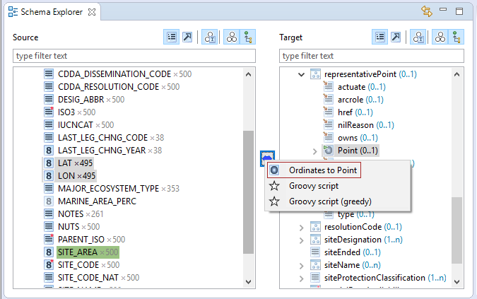
XtoLONand the source forYtoLAT. Also, set the source forztonone, then click «Finish»: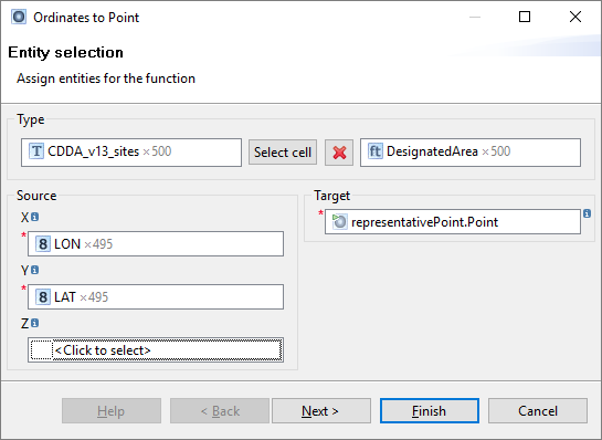
- Perform the same steps of choosing the source and target schema elements and to connect them with a transformation function for the following properties. If the function is accompanies by text in round brackets (...), use these values as parameters:
SITE_CODE← Rename →cddaIdSITE_CODE← Formatted String (DesignatedArea_{SITE_CODE}) →idCDDA_COORDINATES_CODE← Rename →coordinatesCode.hrefCDDA_DISSEMINATION_CODE← Rename →dataDissemination.hrefCDDA_RESOLUTION_CODE← Rename →resolutionCode.hrefPARENT_ISO← Rename →isoCountryCode.hrefISO3← Rename →isoEntityCode.hrefIUCNCAT← Rename →iucnCat.hrefMAJOR_ECOSYSTEM_TYPE← Rename →majorEcosystemType.hrefMARINE_AREA_PERC← Rename →marineAreaPercentageSITE_NAME← Rename →siteName.GeographicalName.spelling.SpellingOfName.textLAST_LEG_CHNG_YEAR← Date Extraction (yyyy) →legalFoundationDateLAST_LEG_CHNG_CODE← Rename →legalFoundationDocument.CI_Citation.title.CharacterString.CharacterStringLAST_LEG_CHNG_YEAR← Rename →legalFoundationDocument.CI_Citation.date.hrefNOTES← Rename →remark
- Now, create property mappings for the
ProtectedSitetype as well. The full mapping table for that is available here.
Now that we've created complete ProtectedSite and DesignatedArea features, we still need to link them. For that purpose, we need to add one more mapping that create a reference from a DesignatedArea to its respective ProtectedSite object:
Note: We generate the ProtectedSite objects in this project as well, but in a real-world implementation, you should reference external, already existing ProtectedSite objects. A reference to an external object depends on a stable, permanent identifier that is resolvable (usually by means of a central registry), and is something that is out of scope for this tutorial. |
- On the left-hand source side, select the property
SITE_CODEin the typeCDDA_v13_sites, on the right-hand target side, pick the attributehrefof the propertysiteDescribedthe typeDesignatedArea. - Click on
 and pick «Formatted String». This function takes any number of input variables and writes out a composite, formatted string. We'll configure it like this:
The anchor (#) allows us to point to another object in the same document by its
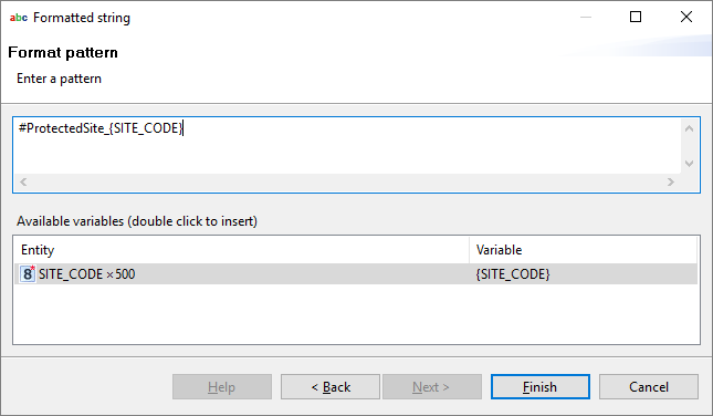
id. - Now, your project should look like this:
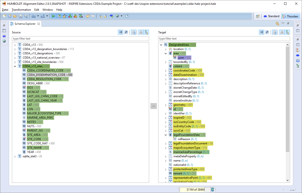
To export the whole data as INSPIRE GML, proceed as follows:
- In the Menu, go to Transformation → Transform External Data... and then pick the downloaded SQLIte file from the list of recent files again (or browse to identify it). Click «Next».
- Pick «GML WFS 2.0 FeatureCollection» and click «Next».
- Pick which file you want to save the result to, and enable validation. Click «Next».
- Configure your CRS options, and click «Next»:
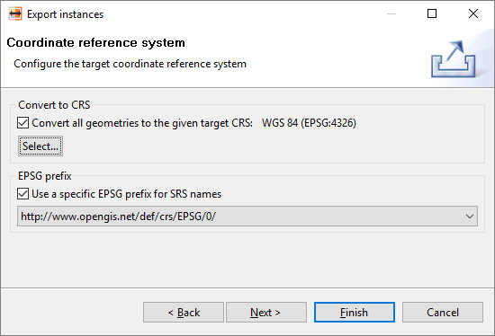
- Bypass the Feed options and leave the default GML options as they are. Click «Finish» and let the transformation run!
Analysis Metrics
Now it's time to check how well the model extension we've designed matches our existing data:
- Model Coverage: Have we actually used all parts of our target model or are there parts where we don't have data? As we can see, there are some properties such as
eionetInstitutewe didn't initially populate, so we can either investiagte where to get matching source data or whether we can remove that property from the model. - Source Data Coverage: Have we been able to map all objects and all properties from the source model to the target model? Looks pretty good, only two fields of the source SQLite table are unmatched:
DESIG_ABBRandNUTSdon't seem to have a place in the CDDA INSPIRE extension. Again we need to decide: Should the next iteration of the model include properties for these values, or should we leave them out? - Instance complexity: How big are the individual instances? do they have a complex net of references? In this case, the instances are relatively simple in structure, with just one reference:
Note that in line 42, we reference theProtectedSiteobject we've also created. - Schema complexity: Is the schema overly complex, e.g. in terms of nesting depth? We have a few places such as
legalFoundationDocumentthat have a high nesting depth. Some tools will benefit from simplification here.
Happy with the outcome? OK, so let's see if we can publish this transformed data set to build a Download Service.
Publication
To publish the resulting INSPIRE GML file we've created, we will use a very simple solution - a deegree Memory Feature Store. This simple approach only works with relatively small data sets, but is by far the fastest way at the time of this writing to get from a complex GML file to a Web Feature Service 2.0 (INSPIRE Direct Access Download Service) and a Web Map Service 1.3.0 (INSPIRE View Service).
| Are you familiar with docker and have already set it up on your machine? Get the deegree3 docker image and run it according to the instructions on the Github repository. It comes with everything you'll need, even advanced setups with a PostGreSQL database backend. |
First, we'll set up deegree's Workspace and an Memory Feature Store.
- Start deegree.
- If you run it locally with default settings, your default browser will be started and will go go to
the services console. If the automatic launch didn't work, access the console by typinghttp://localhost:8080in the location bar of your browser. You should now see the console: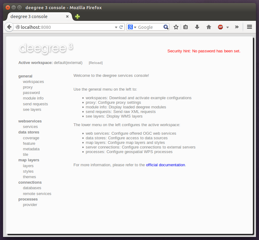
- Click the workspaces link on the left and click the Import link labeled
deegree-workspace-inspire. This will set up an in-memory feature store as well as create a default configuration for a View and a Download Service. After deegree has finished the download, the new workspace will be listed in section «Available workspaces». - As the
deegree-workspace-inspireis pre-configured only for standard INSPIRE Annex I themes, we need to add some configuration for our CDDA schema. Create the Feature Store configuration file in an editor by customizing this example: - Now, go to «data stores/features» and enter a name (e.g.
inspire_cdda), selectMemoryfrom the dropdown, and click «Create New». - The new feature store is now added to the list. Click «Edit»and paste your configuration file in. Save the edits and return to «General/Workspaces».
- Activate the downloaded workspace by clicking Start. This initializes the workspace and may take a while. When the workspace appears next to «Active workspace», your deegree service is now running.
After we've set up the workspace and feature store configuration, we need to write the data we've previously transformed to the feature store. We will do so via deegree's Transactional Web Feature Service (WFS-T) capability, directly from hale studio:
- In hale, open the transformation project we've created previously.
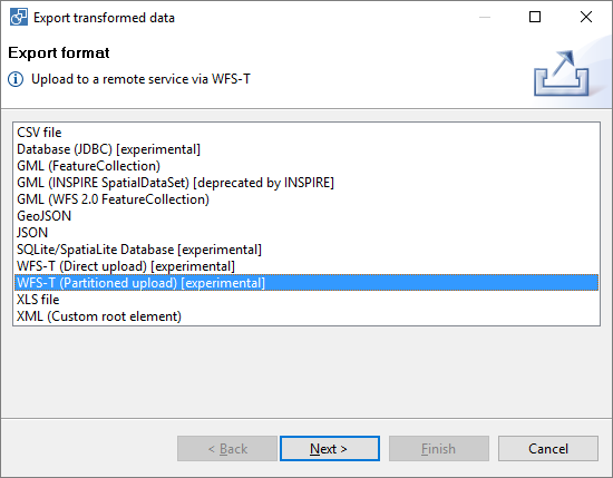
- Go to «File», then to «Export» and «Transformed Data». Pick «WFS-T (Partitioned Upload)» as the export format.
- In the next screen, click the button «...» to the right of the text entry field labelled «Transaction URL». Enter the GetCapabilities URL of your Web Feature Service. Assuming default settings, it will be very similar to
http://localhost:8080/deegree-webservices-3.3.18/services/CDDA?service=WFS&version=2.0.0&request=GetCapabilities. hale will automatically derive the Transaction URL from the capabilities. - Select WFS Version 2.0.0, and click «Next»
- Now, we set the GML writer options. You will get the most reliable results when you explicitly convert and declare the CRS, and since GML mandates counterclockwise polygon ring orientation, be sure to have these settings:
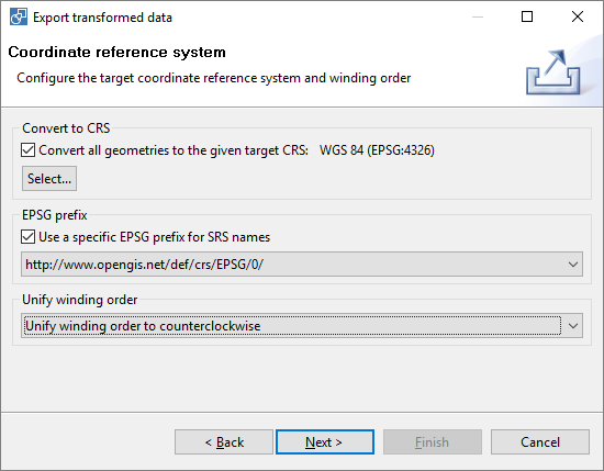
- Click «Next» again, and set the partitioning number. When all your features are small (no big geometries), you can use the default of
15.000, otherwise use a lower number, e.g.1.000. The settings on the following pages can be left as-is, if you didn't change any of deegree's default settings. Click «Finish» and let the transformation and insertion run. - When the transactions have finished, go back to the deegree service console. Here, go to «Home» and click the link «see layers» next to
deegree-workspace-inspire. You should a map like this: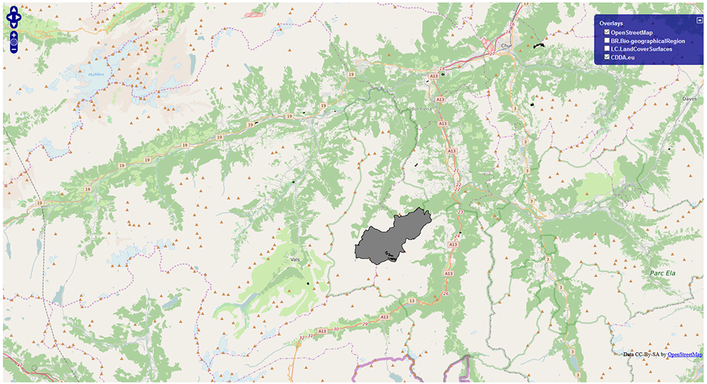
It works? We're done with the first iteration!
Coda
Of course it's not the end yet. You will continue to improve the INSPIRE extension in short and long iterations, and we will also improve this tutorial more and more. Some ideas for the next months:
- You would like to see a different tool added? Let us know!
- You would like to generate services and models online without desktop or server tools? Let us know!
- You would like to see more patterns in the tutorial? Let us know!